-
Call Us On
+91 97695 84950
-
Mail Us @
info@mokshtubes.com
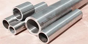
U-Bent Tubes
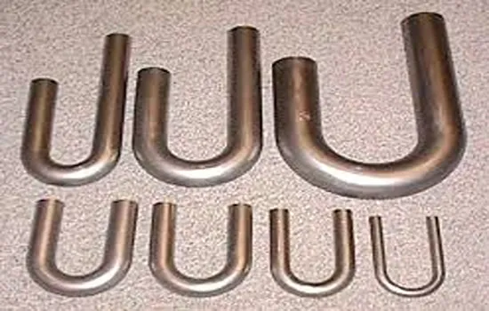
U-Bent Tubes are specially fabricated tubes designed for efficient heat transfer in compact heat exchanger systems. They are bent into a “U” shape to allow the fluid to flow in a reverse direction without requiring separate return piping, thereby saving space and enhancing heat recovery performance.
Moksh Tubes & Fittings LLP, we supply precision-engineered U-Bent Tubes in stainless steel, carbon steel, alloy steel, and nickel alloys. These tubes are widely used in boilers, condensers, and heat exchangers across power, petrochemical, and process industries. All tubes are produced and bent under strict quality control to ensure dimensional accuracy and structural integrity.
- Custom lengths & diameters up to 12 meters
- Available in stainless steel, carbon steel, alloy steel & nickel alloys
- Ideal for power, petrochemical & industrial applications
- Strict quality control ensures dimensional accuracy & durability
Explore our range of industrial piping solutions and find the **perfect U-Bent Tube** for your system.
Specifications
| Category | Details |
|---|---|
| Material | Stainless Steel, Carbon Steel, Alloy Steel, Duplex Steel, Nickel Alloys |
| Grades | ASTM A179, A192, A210, A213, A268, A556, EN10216-2, BS 3059, ASME SA213 |
| Outer Diameter (OD) | 6 mm to 76.2 mm |
| Wall Thickness | 0.5 mm to 8 mm (as per design requirements) |
| Lengths | Up to 12 meters (or as per specification) |
| Bend Radius | Minimum 1.5 x OD or as per customer drawing |
| Finishes | Bright Annealed, Pickled, Polished, Passivated |
| Type | Seamless / Welded |
| Form | U-Bent Form with Straight Leg Extensions |
Charts
Weight Chart
| Nominal Bore Chart | Outside Diameter (O.D) (mm) |
Schedule 5C | Schedule 10C | Schedule 40C | Schedule 80C | Schedule 160C | Schedule XXC | |||||||
|---|---|---|---|---|---|---|---|---|---|---|---|---|---|---|
| mm | inches | Wt | Weight | Wt | Weight | Wt | Weight | Wt | Weight | Wt | Weight | Wt | Weight | |
| 3 | 1/8 | 10.3 | 0.2 | 0.01 | 0.3 | 0.02 | 0.4 | 0.03 | 0.6 | 0.04 | 0.8 | 0.06 | 1.0 | 0.07 |
| 6 | 1/4 | 13.7 | 0.2 | 0.02 | 0.3 | 0.03 | 0.4 | 0.04 | 0.6 | 0.06 | 0.8 | 0.08 | 1.0 | 0.10 |
| 10 | 3/8 | 17.1 | 0.2 | 0.03 | 0.3 | 0.04 | 0.4 | 0.06 | 0.6 | 0.08 | 0.8 | 0.11 | 1.0 | 0.14 |
| 15 | 1/2 | 21.3 | 0.2 | 0.04 | 0.3 | 0.06 | 0.4 | 0.08 | 0.6 | 0.12 | 0.8 | 0.16 | 1.0 | 0.20 |
| 20 | 3/4 | 26.7 | 0.2 | 0.06 | 0.3 | 0.09 | 0.4 | 0.12 | 0.6 | 0.17 | 0.8 | 0.22 | 1.0 | 0.28 |
| 25 | 1 | 33.4 | 0.2 | 0.08 | 0.3 | 0.12 | 0.4 | 0.17 | 0.6 | 0.25 | 0.8 | 0.33 | 1.0 | 0.41 |
| 32 | 1 1/4 | 42.2 | 0.2 | 0.13 | 0.3 | 0.19 | 0.4 | 0.26 | 0.6 | 0.38 | 0.8 | 0.50 | 1.0 | 0.62 |
| 40 | 1 1/2 | 48.3 | 0.2 | 0.16 | 0.3 | 0.24 | 0.4 | 0.32 | 0.6 | 0.48 | 0.8 | 0.63 | 1.0 | 0.78 |
| 50 | 2 | 60.3 | 0.2 | 0.24 | 0.3 | 0.36 | 0.4 | 0.47 | 0.6 | 0.70 | 0.8 | 0.93 | 1.0 | 1.17 |
| 65 | 2 1/2 | 73.0 | 0.2 | 0.33 | 0.3 | 0.49 | 0.4 | 0.65 | 0.6 | 0.97 | 0.8 | 1.29 | 1.0 | 1.63 |
| 80 | 3 | 88.9 | 0.2 | 0.47 | 0.3 | 0.70 | 0.4 | 0.93 | 0.6 | 1.40 | 0.8 | 1.87 | 1.0 | 2.36 |
| 100 | 4 | 114.3 | 0.2 | 0.77 | 0.3 | 1.14 | 0.4 | 1.52 | 0.6 | 2.27 | 0.8 | 3.04 | 1.0 | 3.82 |
| 125 | 5 | 141.3 | 0.2 | 1.17 | 0.3 | 1.72 | 0.4 | 2.30 | 0.6 | 3.42 | 0.8 | 4.58 | 1.0 | 5.76 |
| 150 | 6 | 168.3 | 0.2 | 1.63 | 0.3 | 2.41 | 0.4 | 3.23 | 0.6 | 4.79 | 0.8 | 6.38 | 1.0 | 8.02 |
| 200 | 8 | 219.1 | 0.2 | 2.73 | 0.3 | 4.03 | 0.4 | 5.40 | 0.6 | 8.01 | 0.8 | 10.65 | 1.0 | 13.33 |
| 250 | 10 | 273.1 | 0.2 | 4.17 | 0.3 | 6.15 | 0.4 | 8.23 | 0.6 | 12.23 | 0.8 | 16.27 | 1.0 | 20.35 |
| 300 | 12 | 323.9 | 0.2 | 5.94 | 0.3 | 8.76 | 0.4 | 11.71 | 0.6 | 17.45 | 0.8 | 23.23 | 1.0 | 29.05 |
| 350 | 14 | 355.6 | 0.2 | 7.21 | 0.3 | 10.63 | 0.4 | 14.23 | 0.6 | 21.20 | 0.8 | 28.26 | 1.0 | 35.35 |
| 400 | 16 | 406.4 | 0.2 | 9.29 | 0.3 | 13.70 | 0.4 | 18.35 | 0.6 | 27.37 | 0.8 | 36.46 | 1.0 | 45.59 |
| 450 | 18 | 457.2 | 0.2 | 11.52 | 0.3 | 17.00 | 0.4 | 22.78 | 0.6 | 34.00 | 0.8 | 45.33 | 1.0 | 56.70 |
| 500 | 20 | 508.0 | 0.2 | 13.88 | 0.3 | 20.50 | 0.4 | 27.50 | 0.6 | 41.10 | 0.8 | 54.75 | 1.0 | 68.45 |
| 600 | 24 | 609.6 | 0.2 | 18.93 | 0.3 | 28.00 | 0.4 | 37.50 | 0.6 | 56.05 | 0.8 | 74.68 | 1.0 | 93.95 |
Size Charts
Schedule 5C – Size Chart (ASME B36.10)
| NPS (inches) | NB (mm) | OD (mm) | Wall Thickness (mm) | Internal Diameter (mm) | Weight (kg/m) |
|---|---|---|---|---|---|
| 1/2 | 15 | 21.3 | 1.65 | 18.0 | 0.84 |
| 3/4 | 20 | 26.7 | 1.65 | 23.4 | 1.03 |
| 1 | 25 | 33.4 | 1.65 | 30.1 | 1.3 |
| 1 1/4 | 32 | 42.2 | 1.65 | 38.9 | 1.65 |
| 1 1/2 | 40 | 48.3 | 1.65 | 44.9 | 1.91 |
| 2 | 50 | 60.3 | 1.65 | 56.0 | 2.4 |
| 2 1/2 | 65 | 73.0 | 2.11 | 68.8 | 3.69 |
| 3 | 80 | 88.9 | 2.11 | 84.7 | 4.51 |
| 4 | 100 | 114.3 | 2.11 | 110.1 | 5.84 |
| 5 | 125 | 141.3 | 2.77 | 135.8 | 9.47 |
| 6 | 150 | 168.3 | 2.77 | 162.8 | 11.32 |
| 8 | 200 | 219.1 | 2.77 | 213.6 | 14.79 |
| 10 | 250 | 273.1 | 3.4 | 266.3 | 22.63 |
| 12 | 300 | 323.9 | 3.56 | 317.0 | 31.25 |
| 14 | 350 | 355.6 | 3.96 | 347.7 | 36.96 |
| 16 | 400 | 406.4 | 4.19 | 398.0 | 41.56 |
| 18 | 450 | 457.2 | 4.57 | 448.1 | 49.42 |
| 20 | 500 | 508.0 | 5.54 | 496.9 | 59.25 |
| 22 | 550 | 558.8 | 5.54 | 547.7 | 65.97 |
| 24 | 600 | 609.6 | 5.54 | 598.5 | 82.47 |
Schedule 10C – Size Chart (ASME B36.10)
| NPS (inches) | NB (mm) | OD (mm) | Wall Thickness (mm) | Internal Diameter (mm) | Weight (kg/m) |
|---|---|---|---|---|---|
| 1/2 | 15 | 21.3 | 2.11 | 17.1 | 1.04 |
| 3/4 | 20 | 26.7 | 2.11 | 22.5 | 1.37 |
| 1 | 25 | 33.4 | 2.77 | 27.9 | 2.17 |
| 1 1/4 | 32 | 42.2 | 2.77 | 36.7 | 2.8 |
| 1 1/2 | 40 | 48.3 | 2.77 | 42.8 | 3.25 |
| 2 | 50 | 60.3 | 2.77 | 54.8 | 4.12 |
| 2 1/2 | 65 | 73.0 | 3.05 | 66.9 | 5.6 |
| 3 | 80 | 88.9 | 3.05 | 82.8 | 6.9 |
| 4 | 100 | 114.3 | 3.05 | 108.2 | 9.01 |
| 5 | 125 | 141.3 | 3.4 | 134.5 | 12.28 |
| 6 | 150 | 168.3 | 3.4 | 161.5 | 14.69 |
| 8 | 200 | 219.1 | 3.76 | 211.6 | 20.25 |
| 10 | 250 | 273.1 | 4.19 | 264.7 | 27.86 |
| 12 | 300 | 323.9 | 4.57 | 314.8 | 36.27 |
| 14 | 350 | 355.6 | 4.78 | 346.0 | 41.15 |
| 16 | 400 | 406.4 | 4.78 | 396.8 | 47.14 |
| 18 | 450 | 457.2 | 4.78 | 447.6 | 53.05 |
| 20 | 500 | 508.0 | 5.54 | 496.9 | 66.75 |
| 22 | 550 | 558.8 | 5.54 | 547.7 | 73.46 |
| 24 | 600 | 609.6 | 6.35 | 596.9 | 86.78 |
Schedule 40C – Size Chart (ASME B36.10)
| NPS (inches) | NB (mm) | OD (mm) | Wall Thickness (mm) | Internal Diameter (mm) | Weight (kg/m) |
|---|---|---|---|---|---|
| 1/8 | 3 | 10.3 | 1.73 | 6.84 | 0.37 |
| 1/4 | 6 | 13.7 | 2.24 | 9.22 | 0.84 |
| 1/2 | 15 | 21.3 | 2.77 | 15.7 | 1.27 |
| 3/4 | 20 | 26.7 | 2.87 | 21.0 | 1.69 |
| 1 | 25 | 33.4 | 3.38 | 26.6 | 2.50 |
| 1 1/4 | 32 | 42.2 | 3.56 | 35.1 | 3.39 |
| 1 1/2 | 40 | 48.3 | 3.68 | 41.0 | 4.05 |
| 2 | 50 | 60.3 | 3.91 | 52.5 | 5.44 |
| 2 1/2 | 65 | 73.0 | 5.16 | 62.7 | 8.63 |
| 3 | 80 | 88.9 | 5.49 | 78.9 | 11.3 |
| 3 1/2 | 90 | 101.6 | 5.74 | 90.1 | 13.6 |
| 4 | 100 | 114.3 | 6.02 | 102.3 | 16.1 |
| 5 | 125 | 141.3 | 6.55 | 128.2 | 21.8 |
| 6 | 150 | 168.3 | 7.11 | 154.1 | 28.3 |
| 8 | 200 | 219.1 | 8.18 | 202.7 | 42.6 |
| 10 | 250 | 273.0 | 9.27 | 254.5 | 60.3 |
| 12 | 300 | 323.8 | 10.31 | 303.2 | 79.7 |
| 14 | 350 | 355.6 | 11.13 | 333.4 | 94.6 |
| 16 | 400 | 406.4 | 12.70 | 381.0 | 123.3 |
| 18 | 450 | 457.2 | 14.27 | 428.7 | 155.8 |
| 20 | 500 | 508.0 | 15.09 | 477.8 | 183.4 |
| 24 | 600 | 610.0 | 17.48 | 575.0 | 255.4 |
Schedule 80C – Size Chart (ASME B36.19)
| NPS (inches) | NB (mm) | OD (mm) | Wall Thickness (mm) | Internal Diameter (mm) | Weight (kg/m) |
|---|---|---|---|---|---|
| 1/8 | 3 | 10.3 | 2.41 | 5.48 | 0.47 |
| 1/4 | 6 | 13.7 | 3.02 | 7.66 | 1.06 |
| 1/2 | 15 | 21.3 | 3.73 | 13.84 | 1.61 |
| 3/4 | 20 | 26.7 | 3.91 | 18.88 | 2.34 |
| 1 | 25 | 33.4 | 4.55 | 24.3 | 3.37 |
| 1 1/4 | 32 | 42.2 | 4.85 | 32.5 | 4.66 |
| 1 1/2 | 40 | 48.3 | 5.08 | 38.1 | 5.57 |
| 2 | 50 | 60.3 | 5.54 | 49.2 | 7.57 |
| 2 1/2 | 65 | 73.0 | 7.01 | 59.0 | 11.3 |
| 3 | 80 | 88.9 | 7.62 | 73.7 | 15.7 |
| 3 1/2 | 90 | 101.6 | 8.08 | 85.4 | 19.1 |
| 4 | 100 | 114.3 | 8.56 | 97.2 | 23.0 |
| 5 | 125 | 141.3 | 9.53 | 122.2 | 31.4 |
| 6 | 150 | 168.3 | 10.97 | 146.4 | 41.5 |
| 8 | 200 | 219.1 | 12.70 | 193.7 | 63.6 |
| 10 | 250 | 273.1 | 15.09 | 243.0 | 93.2 |
| 12 | 300 | 323.9 | 17.48 | 288.9 | 124.3 |
| 14 | 350 | 355.6 | 19.05 | 317.5 | 147.2 |
| 16 | 400 | 406.4 | 21.44 | 363.5 | 185.5 |
| 18 | 450 | 457.2 | 23.83 | 409.5 | 227.6 |
| 20 | 500 | 508.0 | 26.19 | 455.6 | 276.5 |
| 24 | 600 | 609.6 | 28.58 | 552.4 | 366.3 |
Schedule 160C – Size Chart (ASME B36.10)
| NPS (inches) | NB (mm) | OD (mm) | Wall Thickness (mm) | Internal Diameter (mm) | Weight (kg/m) |
|---|---|---|---|---|---|
| 1/2 | 15 | 21.3 | 4.78 | 11.7 | 1.97 |
| 3/4 | 20 | 26.7 | 5.56 | 15.6 | 3.09 |
| 1 | 25 | 33.4 | 6.35 | 20.7 | 4.56 |
| 1 1/4 | 32 | 42.2 | 6.35 | 29.5 | 6.09 |
| 1 1/2 | 40 | 48.3 | 7.14 | 34.0 | 7.89 |
| 2 | 50 | 60.3 | 8.74 | 42.8 | 11.5 |
| 2 1/2 | 65 | 73.0 | 9.53 | 53.9 | 15.9 |
| 3 | 80 | 88.9 | 11.13 | 66.6 | 22.1 |
| 4 | 100 | 114.3 | 13.49 | 87.3 | 34.3 |
| 5 | 125 | 141.3 | 15.88 | 109.5 | 49.1 |
| 6 | 150 | 168.3 | 18.26 | 131.8 | 66.9 |
| 8 | 200 | 219.1 | 23.01 | 173.1 | 108.9 |
| 10 | 250 | 273.1 | 28.58 | 216.0 | 168.6 |
| 12 | 300 | 323.9 | 33.32 | 257.3 | 240.4 |
Schedule XXC – Size Chart (ASME B36.10)
| NPS (inches) | NB (mm) | OD (mm) | Wall Thickness (mm) | Internal Diameter (mm) | Weight (kg/m) |
|---|---|---|---|---|---|
| 1/2 | 15 | 21.3 | 7.47 | 6.36 | 2.86 |
| 3/4 | 20 | 26.7 | 7.82 | 11.06 | 4.46 |
| 1 | 25 | 33.4 | 9.09 | 15.22 | 6.56 |
| 1 1/4 | 32 | 42.2 | 9.70 | 22.80 | 9.45 |
| 1 1/2 | 40 | 48.3 | 10.15 | 28.00 | 11.3 |
| 2 | 50 | 60.3 | 11.07 | 38.16 | 15.3 |
| 2 1/2 | 65 | 73.0 | 14.02 | 44.96 | 23.3 |
| 3 | 80 | 88.9 | 15.24 | 58.42 | 30.8 |
| 4 | 100 | 114.3 | 17.12 | 80.06 | 44.1 |
| 5 | 125 | 141.3 | 19.05 | 103.2 | 62.5 |
| 6 | 150 | 168.3 | 21.95 | 124.4 | 84.7 |
| 8 | 200 | 219.1 | 25.40 | 168.3 | 122.6 |
| 10 | 250 | 273.1 | 31.75 | 209.6 | 184.8 |
| 12 | 300 | 323.9 | 38.10 | 247.7 | 260.5 |
Grades Available
U-Bent Tubes are available in a wide range of grades:
| Material | Grades |
|---|---|
| Carbon Steel | ASTM A179, A192, A210 Gr A1/C |
| Alloy Steel | ASTM A213 T11, T12, T22, T91, T5, T9 |
| Stainless Steel | TP304, 304L, 316, 316L, 321, 347, 310, 904L |
| Duplex / Super Duplex | UNS S31803, S32205, S32750, S32760 |
| Nickel Alloys | Inconel 600, 625, 800, 825, Monel 400, Hastelloy C22, C276, Alloy 20 |
NICKLE ALLOYS
STAINLESS STEEL
DUPLEX & SUPER
TITANIUM ALLOYS

Haynes Superalloys
Inconel
Applications
U-Bent Tubes are essential in thermal systems where compactness, efficiency, and heat transfer performance are required:
Heat Exchangers
- Shell & Tube type for petrochemical plants and refineries
Boilers & Superheaters
- For return fluid and steam generation loops
Condensers & Economizers
- Used in power generation systems and HRSGs
Chemical & Fertilizer Plants
- Urea, ammonia, and nitric acid production systems
Desalination Plants
- Thermal distillation and brine concentration units
HVAC & Refrigeration Systems
- Compact heat exchange coils
Uses of Welded U-Bent Tubes
U-Bent Tubes are used extensively across multiple industries, including:
Piping System Optimization
Reduces the need for pipe fittings and welding joints
Compact Thermal Design
Ensures compact design for thermal systems
High-Pressure Reliability
Enhances mechanical strength in high-pressure loops
Uniform Heat Distribution
Maintains uniform heat distribution across thermal networks
Efficient Flow Management
Minimizes pressure drop and turbulence in flow systems
Versatile System Integration
Supports integration into diverse thermal and fluid systems with ease
Advantages of U-Bent Tubes
Space Saving Design
Ideal for compact heat exchanger layouts
High Heat Transfer Efficiency
Smooth ID and accurate bending
Pressure & Temperature Resistance
Engineered for demanding applications
Dimensional Precision
CNC-controlled bending, minimal ovality and thinning
Corrosion Resistance
Suitable for harsh and acidic process environments
WHY CHOOSE US?
FAQ's
What are U-Bent Tubes used for?
U-Bent Tubes are used in heat exchangers, condensers, boilers, and other thermal systems to facilitate fluid return flow in compact designs. Their U-shaped configuration allows efficient heat transfer while reducing the need for extra fittings or space.
What materials are available for U-Bent Tubes?
U-Bent Tubes are available in a wide range of materials including Stainless Steel, Carbon Steel, Alloy Steel, Duplex & Super Duplex, and Nickel Alloys. Each material is selected based on the required temperature, pressure, and corrosion resistance for the application.
What are the key advantages of using U-Bent Tubes?
U-Bent Tubes offer multiple benefits such as compact design, high heat transfer efficiency, and reduced pressure drop. They also provide exceptional corrosion resistance, dimensional precision, and can handle high pressure and temperature conditions efficiently.
Which industries commonly use U-Bent Tubes?
U-Bent Tubes are used in power generation, petrochemical, fertilizer, chemical, desalination, and HVAC industries. They play a key role in heat exchangers, condensers, boilers, and economizers for efficient energy recovery.
What testing and inspection standards are followed?
All U-Bent Tubes supplied by Moksh Tubes & Fittings LLP undergo rigorous quality checks, including Non-Destructive Testing (NDT), Eddy Current, Hydrostatic, and PMI tests. Third-party inspection and ISO 9001:2015 compliance ensure superior quality and reliability.
Can U-Bent Tubes be customized for specific designs?
Yes, U-Bent Tubes can be custom-fabricated in various diameters, lengths (up to 12 meters), and bend radii as per customer drawings. CNC-controlled bending ensures minimal ovality, thinning, and perfect dimensional precision.
Contact Us
For further information, quotes, or customized u-bent-tube products, Moksh Tubes & Fittings LLP your dependable partner in aluminum alloys.
Get in Touch